End Fed Half Wave Antennas
- End Fed Half Wave Antenna
Description:
Updated! Sep 2024 - EFHW References:
- Kit Constructors Alert:
- 49:1 Autotransformer KIT
Notes:
NEW! Sep 2024 - 49:1 EFHW Tests:
NEW! Sep 2024 - Product Changes and Updates:
- Buy A 49:1 EFHW Autotransformer Kit:
The End Fed Half Wave Antenna using a 49:1 or 64:1 Transformer is one of the most popular Antennas used in the world. The Antenna typically uses a wire length that is cut to a half wave length for the lowest frequency band, and will work on harmonically related bands up to the 10m band which is the limit of the Transformer. So for an Antenna that is cut for the 40m band, it will also work on both the 20 and 10m bands. A longer 40m length will cover the 80 to 10m bands including all the WARC bands. In most cases if the Antenna is constructed correctly, then only an internal tuner is required on some bands to reduce SWR. There are various optional options including loading coils compensation coils, and capacitors that can be used to optimize the tuning on some bands. I personally don't bother with using compensation coils and series capacitors as it adds more complexity when the Antenna can be easily matched with an internal tuner. End fed Antennas have been around for a very long time, and using a 49:1 Transformer is no different to using a long wire tuner or AH4 or similar auto tuner. The bonus with using a 49:1 Transformer is that is can be constructed at low cost and get you onto the HF bands quickly.
These references are useful to start researching the various designs.
1/ The End-Fed Half-Wave Antenna by Steve Dicks K1RF
2/ YouTube Videos by Colin MM0OPX
3/ Understanding End Fed Half Wave Antennas and its Half Wave Multiples by Hans PA0SNY
The EFHW 49:1 Autotransformer Kit is suitable for construction of an efficient End Fed Half Wave Antenna for the 3.5 ( 80m ) to 30MHz ( 10m ) bands. The required Antenna wire length required is approximately a half wave length at the lowest frequency, i.e. 40m for the 80m Band, or 20m for the 40m band. A 40m length will cover all harmonically related bands including the WARC bands from 80 to 10m. A 20m length will cover 40, 20 and the 10m Bands.
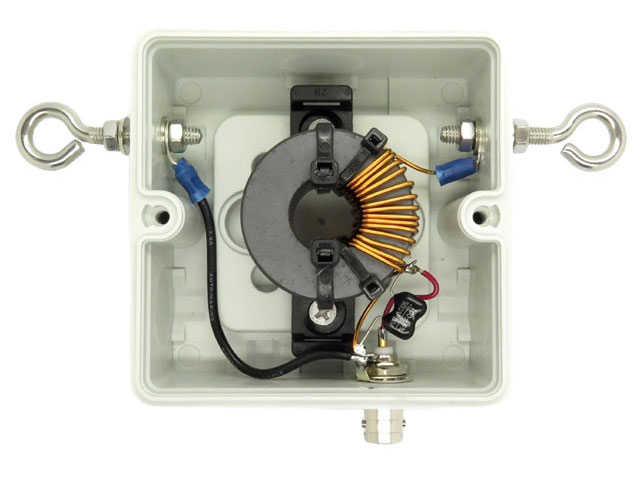
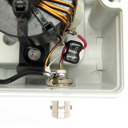
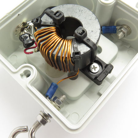
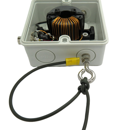
The Autotransformer uses a Fair-rite 43 material 2643251002 Toroidal Bead, and consists of 14 turns of 1mm ECW wound tightly against the core tapped at 2 turns. A 100pF Mica capacitor is used on the 2 turn primary to provide a better match above 20MHz. The Kit is quite straightforward to construct, so mainly pictures are supplied showing how the mechanical parts are assembled. It is up to the constructor to research EFHW Antennas on recommended Antenna wire lengths and installation for best performance.
The counterpoise eyelet hook is used to attach the Autotransformer to a support mast. Never directly connect the counterpoise eyelet to a metal mast. Make sure that you use nylon cord or an insulator.
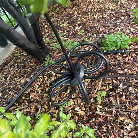
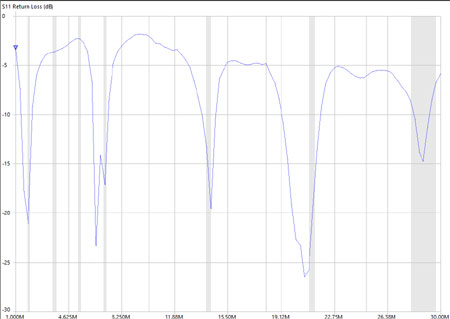
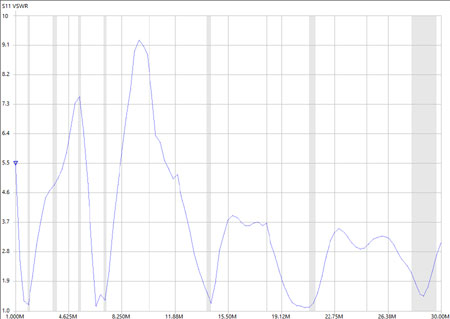
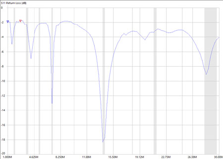
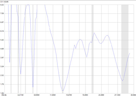
The tests below show two EFHW Antennas that are used by VK5LO. Both Antennas are around 8m high and horizontally mounted. A counterpoise and choke is always required with these types of Antennas. The choke is used to block RF on the coax outer getting back to the Transceiver, and also stops common mode noise from the Radio shack getting to the Antenna via the Transformer. For common mode noise suppression and to be able to provide a counterpoise, the coaxial cable feed lines are wound 6 to 8 turns through an FT140 or FT240 43 material ferrite at a distance from the Autotransformer. The distance is around 2 metres for the 40m band EFHW, and 4 metres for the 80m band version. The distance is not critical and improves the Antennas performance. Tests have not been made with different counterpoise lengths.
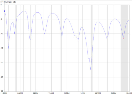
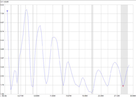
The 80m version ( ~42m long ) will cover the complete 3.5 to 28MHz bands including WARC. Only a small touch up with the internal tuner is required on some bands for low SWR. Performance is excellent producing multiple lobes on the higher bands for DX. The other Antenna was originally made for the 20 and 10m bands and was ~9.5m long. A 34uH loading coil and ~ 2m of extra wire was added to also provide the 40m band as a backup Antenna. The performance on the 20m band is excellent on this Antenna.
The results using loading coils for both 40m ( 34uH ) and the 80m band ( 110uH ) is very much a compromise and did not work well. Signals were a couple S units down on those bands but it does work.

